https://en-forum.supla.org/viewtopic.php?p=31757#p31757
Supla Button 4 direct links
-
ritual

- Posts: 80
- Joined: Mon Apr 20, 2020 11:47 am
is there any simplified wiring for wemos d1 or nodemcu?elmaya wrote: ↑Mon Jan 28, 2019 3:40 pm 4 direct links for battery use
4 direct links button: L1-L4
wificonfig button: config
connect EN to VCC to allow programming
the process is slow (5 or 6 seconds) due to connection to wifi
virtually no standby consumption using chip-enable
add resistor 220k Ohm to suspend Flash in standby mode
Initial parameters for "ESP Falsh Download Tool":
CreystalFreq 26M
SPI SPEED 40 MHz
SPI MODE QIO
BAUDRATE 11520
FLASH SIZE 32Mbit (4MByte)
D_Link_LowPower_x4.bin ------------> 0x00000
because if i connect the pin to ground it goes in loop and turns on and off the device
-
elmaya
- Posts: 1482
- Joined: Wed Jun 27, 2018 5:48 pm
- Location: El Saucejo - Sevilla
nodemcu and wemos have a pullup resistor connected to "EN" that keeps ESP8266 on.
you have to remove that resistor.
Please tell me what specific module you are using and I can tell you what resistor you have to remove.
you have to remove that resistor.
Please tell me what specific module you are using and I can tell you what resistor you have to remove.
-
ritual
- Posts: 80
- Joined: Mon Apr 20, 2020 11:47 am
I am using wemos d1mini.
And do you have any software for 6xD-link for battery use?
P.s. it is good to have you back.

You do not have the required permissions to view the files attached to this post.
-
elmaya
- Posts: 1482
- Joined: Wed Jun 27, 2018 5:48 pm
- Location: El Saucejo - Sevilla
You do not have the required permissions to view the files attached to this post.
-
ritual
- Posts: 80
- Joined: Mon Apr 20, 2020 11:47 am
Thank you.i will try this today.
Do you have any software for 6 direct link with battery use?
Do you have any software for 6 direct link with battery use?
-
elmaya
- Posts: 1482
- Joined: Wed Jun 27, 2018 5:48 pm
- Location: El Saucejo - Sevilla
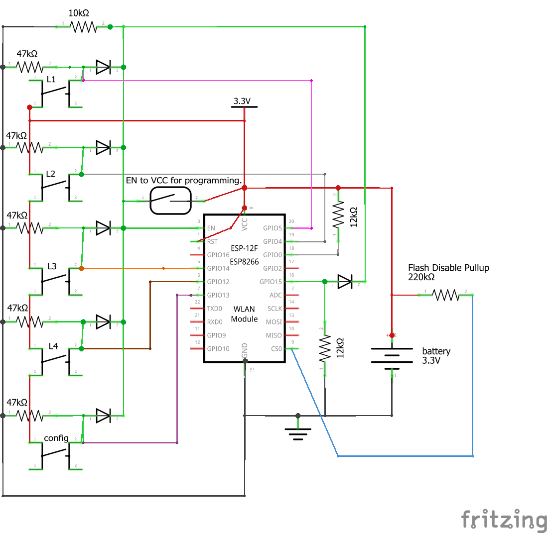
here you have the scheme for Wemos.
I explain a little how it works:
In this design, in order to reduce the energy consumption to a minimum, I have chosen to use the "EN" pin "chip enable" of the Esp8266.
This Pin activates the Esp8266 if it is at a high level and disconnects it if it is at a low level.
in normal conditions we have the "EN" Pin at low level and the Esp8266 is deactivated "for this you had to remove the resistance in the Wemos"
To activate the Esp8266 we have to set the "EN" Pin to high level, this is done with the pushbuttons that in addition to putting the corresponding input Gpio at high level when they are pressed also feed the "EN" Pin through the diodes D1 - D5.
With this, the Esp8266 starts and we set Gpio 15 "D8" to high level, through D6 the "EN" Pin remains high for as long as necessary to send the link, then "D8" goes low and the Esp8266 turns off.
R7 disables the Flash memory chip when the Esp8266 is disabled, it is not essential but reduces consumption by a couple of milliamps.
maybe I can add one or two more links but right now I don't have time for this.
You do not have the required permissions to view the files attached to this post.
-
ritual
- Posts: 80
- Joined: Mon Apr 20, 2020 11:47 am
No problem, thank you for explaining this.elmaya wrote: ↑Sat May 29, 2021 6:42 pm here you have the scheme for Wemos.
wemosD1_bb.png
I explain a little how it works:
In this design, in order to reduce the energy consumption to a minimum, I have chosen to use the "EN" pin "chip enable" of the Esp8266.
This Pin activates the Esp8266 if it is at a high level and disconnects it if it is at a low level.
in normal conditions we have the "EN" Pin at low level and the Esp8266 is deactivated "for this you had to remove the resistance in the Wemos"
To activate the Esp8266 we have to set the "EN" Pin to high level, this is done with the pushbuttons that in addition to putting the corresponding input Gpio at high level when they are pressed also feed the "EN" Pin through the diodes D1 - D5.
With this, the Esp8266 starts and we set Gpio 15 "D8" to high level, through D6 the "EN" Pin remains high for as long as necessary to send the link, then "D8" goes low and the Esp8266 turns off.
R7 disables the Flash memory chip when the Esp8266 is disabled, it is not essential but reduces consumption by a couple of milliamps.
maybe I can add one or two more links but right now I don't have time for this.